LTE Gateway - the build
“In theory, there is no difference between theory and practice. But, in practice, there is.” – overheard at a CS conference by Walter Savitch
In the previous post, we went over the theory of building a LTE gateway.
In the build phase, I obtained a Mikrotik RB2011, a 9AH SLA battery, a PicoUPS, a Sierra Wireless MC7430 in a miniPCIe to USB converter, two RFI XG884 antennas and some patch leads.
And here’s the finished product.
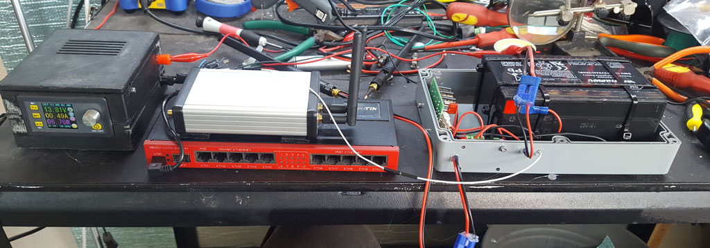
The build process began with getting the router to talk to the modem.
The modem…
Turns out we’ve hit an issue already. Older 2G and 3G modems generally appeared as a serial port to the host and standard AT commands were used to establish a PPP session - just like a dialup modem (but much faster).
However, LTE is different. The network, in addition to being faster, is purely IP based rather than packet data being run over a circuit switched connection. Things had to change and this means that every vendor wrote their own standards. They’ve got one thing in common though - all look much more like an ethernet connection than a serial port. Standardisation did eventually happen - resulting in the MBIM standard being supported by nearly all modems - including the one we have.
RouterOS MBIM support, however, is “coming in RouterOS v7” - which the extensive development time of is a “Duke Nukem Forever” type joke in the networking industry.
We’re not completely out of luck - the modem does still support old fashioned serial. However, we have to do dirty hackarounds to make it work (that took annoyingly long to discover) and the speed will likely be limited to about 30mbit. Also, irritatingly, this modem does not support using one of the alternate serial channels for the PPP session so that you can still query modem statistics while connected. I guess because the PPP channel wasn’t actually meant to be used.
I’m tempted to investigate alternative embedded devices - maybe use something to route the 4G to Ethernet, and then use the Mikrotik just as an access point. But I guess this works for now. Speed testing shows about 30mbit, which is certainly enough.
I mounted the miniPCIe to USB converter into a metal box that I was previously using for another application (hence the strange holes), using some PCB standoffs. This made it a nice discrete box with a USB OTG cable connecting it to the RB2011’s USB port. Some u.fl to SMA pigtails (mistakenly ordered years ago when I really wanted RP-SMA) provide external connectors for the antennas.
GPS
The modem also has GPS functionality. There’s a third antenna connector which can have a GPS antenna connected to it, and apparently with the right AT commands the GPS can be enabled. RouterOS for some reason does fully support GPS receivers, and I could write a simple script to post location updates to StackPtr. This will probably be developed later. (I wish RouterOS shipped gpsd…)
Antennas
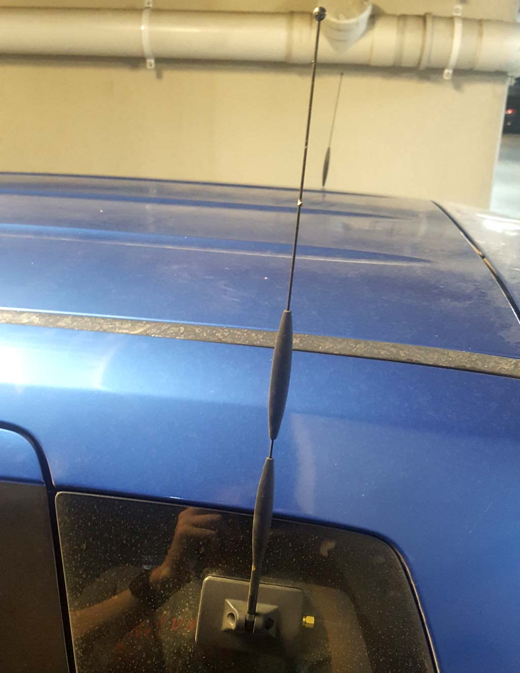
Sticky bit with the antenna goes on the outside. Sticky bit with the connector goes on the inside. Reconsider your decision to use through-glass antennas, but it’s too late now. Don’t have tinted windows, and don’t stick them over metallic window edges or demister wires. Simple. (Strangely enough I saw a car today drive past with one of these on the front bumper! I wonder if the “inside” unit was on the back of the body panel - hopefully it’s fibreglass not metal!)
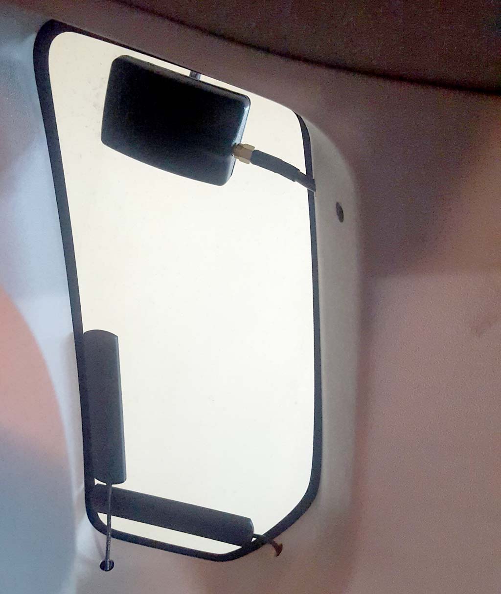
The WiFi antennas just go on the inside of the window. One was placed horizontally and one vertically for maximum MIMO-ness.
Protip: own a set of coax crimpers so that you can run the cable through a cable sized hole, then put the connector on. (Well I have a set now…)
More protip: don’t drill a hole in the wrong place. Oops.
Battery
The PicoUPS works, and works quite well. Without the engine started, the battery does not get charged as the voltage is <13v, which is good. With the car started, the battery charges. The Mikrotik router does not reboot as the car is being started (a common problem with some similar setups). What we need now is to shut down if the car’s off and the router’s not being used.
Initially, I was going to use one of the router’s LEDs to control a relay which disconnects the router’s battery, but it turns out after some desoldering work, the LEDs are all switched in the “current sink” configuration where it’s the negative side, not the positive side that is switched. This makes them incompatible with any of the relay boards I have.
Battery power
The USB port power, however, is switched from the high side - much easier to work with. The relay board disconnects the battery from the PicoUPS when the USB power is turned off. With the car running, the router is booted with USB power enabled. The PicoUPS is charging the router’s battery. A script is running on the Mikrotik every few seconds checking for wireless clients. If none are detected, a timer is decremented, otherwise the timer is reset. When the timer reaches zero, the USB power is switched off then a few seconds later back on again.
If the USB power is turned off while the car is switched on, the relay opens and the battery will be disconnected. The modem will temporarily lose power, but the router remains powered from the car power and stays running to switch the USB power back on again, reconnecting the modem and battery.
If the USB power is turned off while the car is switched off, opening the relay disconnects the battery. This will disconnect power to the router, so the battery will remain disconnected until the car is restarted. Since the battery is disconnected by a relay, there’s no standby power draw.
Now let’s install it
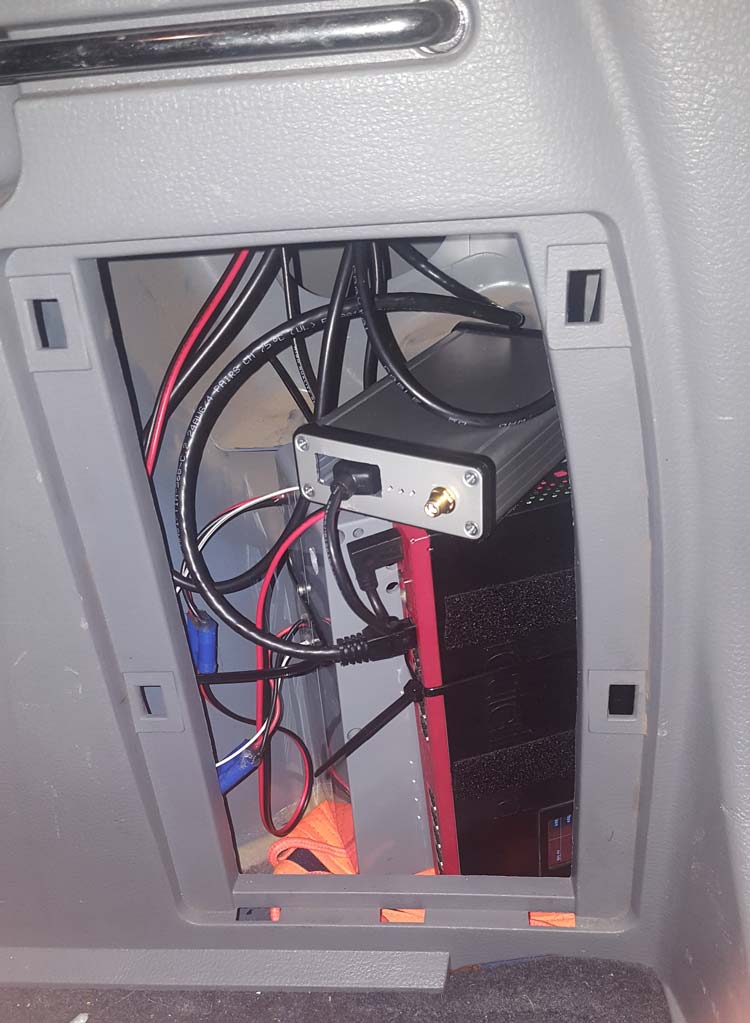
(The unused SMA connector is for the GPS antenna, LTE antenna connections are on the back. The Ethernet cable comes out under the dashboard on the passenger side - figured I may as well run it while already popping the trim panels to run the power cable. Yes, the power connectors are all EC3s.)
It’s been in the car for a few weeks and has undergone some testing. It definitely has signal in places that mobile phones don’t - but it’s not magic. Sometimes the modem doesn’t re-acquire the mobile network after losing it - a USB power reset fixes that. This has only happened twice in a few weeks - maybe it would recover if I was more patient.
The WiFi works quite well outside the car too - I need to try it with a similarly powerful card at the other end to get the most out of the RB2011’s 30dbm (1W) TX power.
Overall I’m quite happy with how this turned out.
Later: we rebuild the gateway for better performance.