LTE Gateway - the rebuild
Previously, we talked about building a LTE-WiFi gateway, and then we built a LTE-WiFi gateway.
There was just one major issue with it - the modem operates in serial mode, due to RouterOS v6 having no MBIM support (RouterOS v7 does but it’s still unreleased).
For a while now I was considering using another device to do the routing - like a Raspberry Pi, oDroid or Beaglebone. But I wanted one that booted quickly, isn’t SD card based (I have replaced so many cards at inconvenient times) and I wanted something that is less picky about power input.
On Twitter. I saw that @decryption bought a Mikrotik RBM11G to run ROOTer - an OpenWRT based firmware that is designed specifically to route a LTE modem.
The RBM11G looks nice - wide DC input, gigabit ethernet, miniPCIe slot. Running something that has a newer kernel than RouterOS v6 would give me MBIM support and might also stop the random dropouts that require power cycling the modem to make it seen again. I have a suspicion it’s either related to the unsupported PPP serial or maybe the RB2011’s USB hardware. Either way this fixes it.
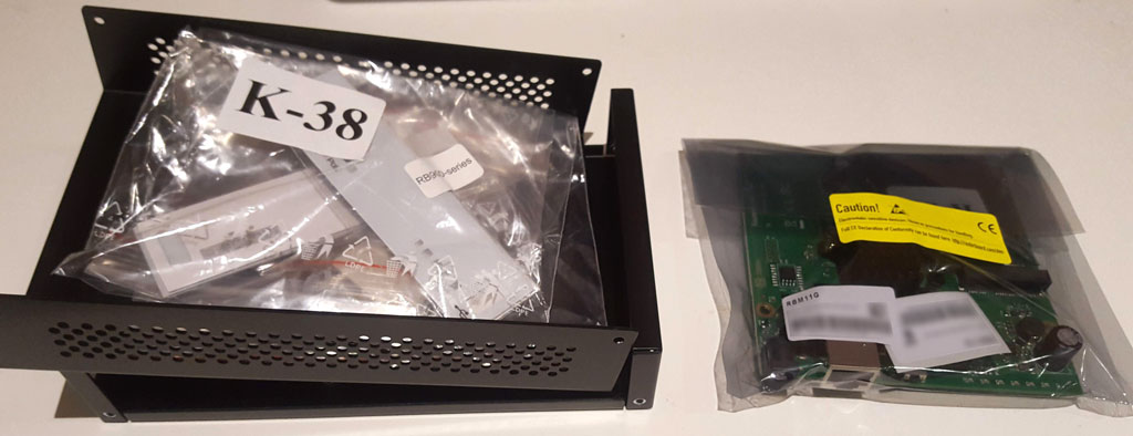
So I ordered the RBM11G and a CA411-711 case from EuroDK.
Read on and we’ll put it all together then install it in the car.
First up is flashing ROOTer onto the device. Back up your RouterOS license key - it will be lost when you reflash and you’ll need it to put RouterOS back on the board. Then follow the instructions here to install ROOTer.
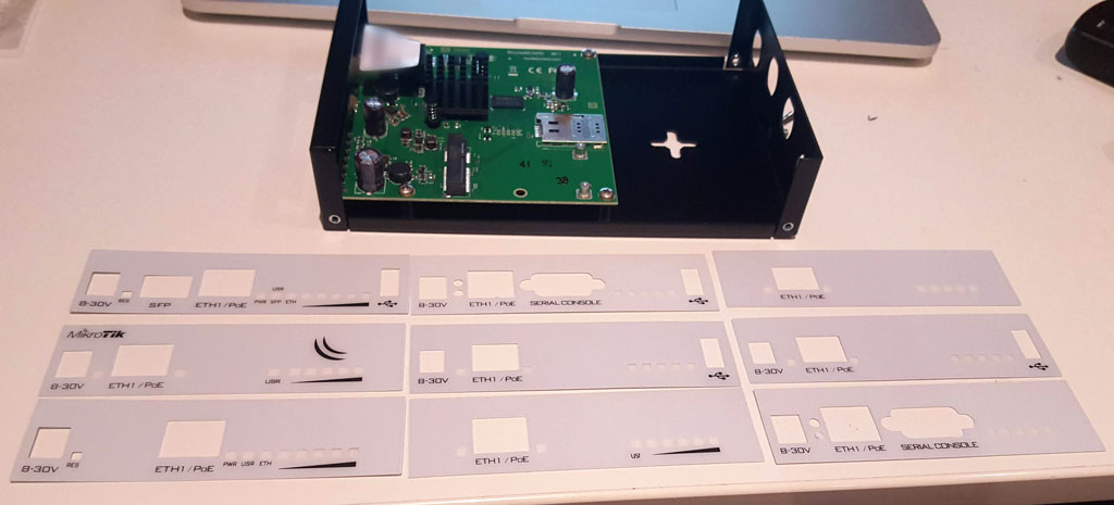
The case has selectable front panels depending on what you’re mounting in it.
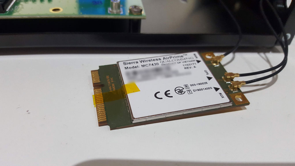
With that fitted, I put the modem card into the RBM11G. When the device was booted, the modem did not show up. This is a common problem with Sierra Wireless cards - they have a USB3 interface connected to the pins that are used for PCIe. If the device you insert it into has PCIe connected to those pins, the modem may try to use USB3 mode and won’t show up to your USB2 host. The fix is reasonably simple - tape over the 6 pins in question. I used Kapton tape but you could probably get away with whatever’s in your stationary drawer.
Once the modem showed up, it did not have the MBIM interface enabled. Running the following AT commands on it fixed that - you can even do this from ROOTer’s web interface.
AT!ENTERCND="A710"
AT!USBCOMP=1,1,100D
AT!RESET
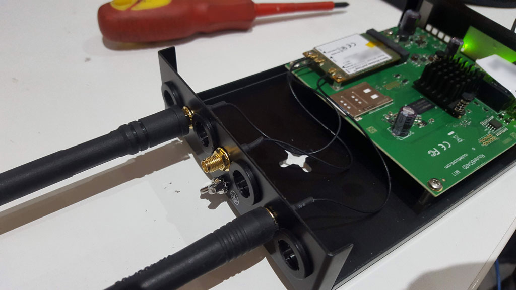
The case, though, I’m not entirely happy with. The antenna ports in the back of the case are designed to fit Mikrotik’s snap-in fixed antennas (the kind that I removed from the RB2011 in the previous build) - not SMA connectors. I suppose I could have 3D printed some sort of adaptor but I just drilled holes in the metal.
In addition to this, it’s significantly bigger than it needs to be. It’s really sized for the larger boards not the RBM11G.
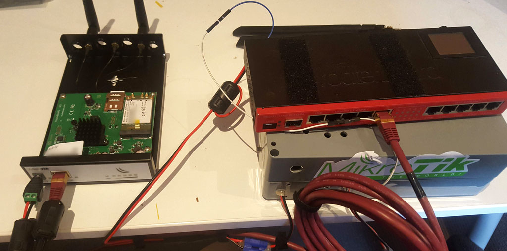
You’ll notice here that power cable is an EC3, not an Anderson PowerPole. My excuse is that I didn’t have an amateur radio license then.
The power cable that previously just supplied the RB2011 has been modified to have a second head to supply the RBM11G as well. A Cat6 STP ethernet cable has been placed between them - shielded was used in order to minimise interference with and from HF radio in the car. It’s a little too long as it was the shortest one I had spare.
I do have some regrets that I didn’t buy the RBM33G instead. $10 more and I could have had two more ethernet ports and another miniPCIe - I could have fitted a WiFi card into the other slot, rather than keeping the existing RB2011. However, I’ve already got the RB2011 working as an access point and switch, as well as it being successfully interfaced with the power setup, so I might keep it around for that.
That, or later purchase the RBM33G anyway and put a second LTE modem in and have dual-WAN to fill blackspots.
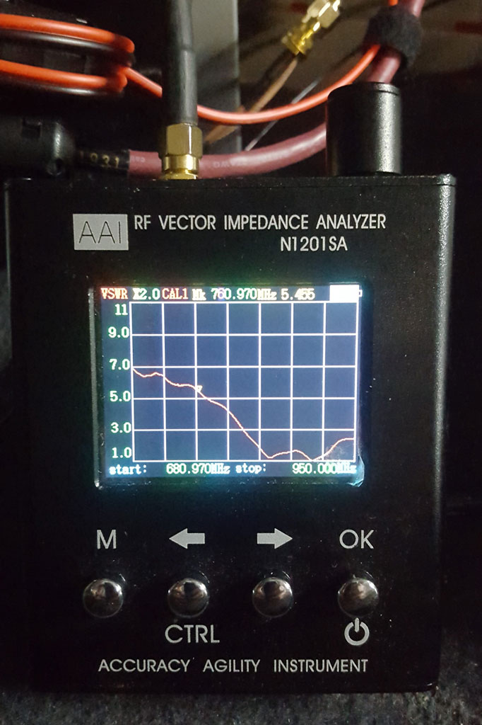
So now let’s get it back into the car - with a test on the inexpensive antenna analyzer to see what exactly it is like at 700mhz - the answer is “not great”. But, it gets something out.
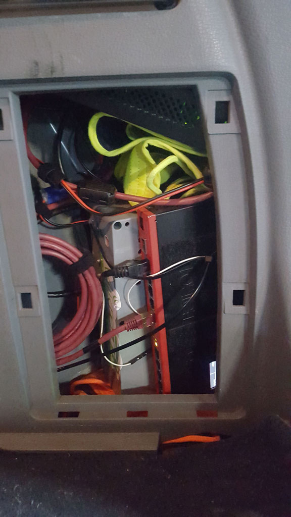
A little strategic placing of things gets the RBM11G stuck in at the top, connected to the external LTE antennas, with the battery and RB2011 where they were. I didn’t mention it last time - but this compartment is actually for storing the jack and wheel brace. However, there’s ample room for them where the spare tyre is kept, so they’re now down there with it, letting us use this space for something else. Another dreaded high-visibility hat stops it from banging on the other devices (never worn, on account of how completely stupid it looks).
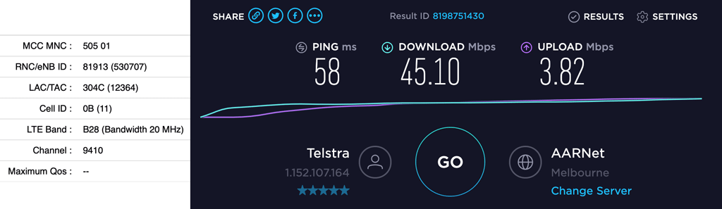
A quick speed test on B28 (700MHz FDD) while stationary - and now using the ROOTer web interface I can see modem parameters:
And again on B3 (1800MHz FDD) while mobile:
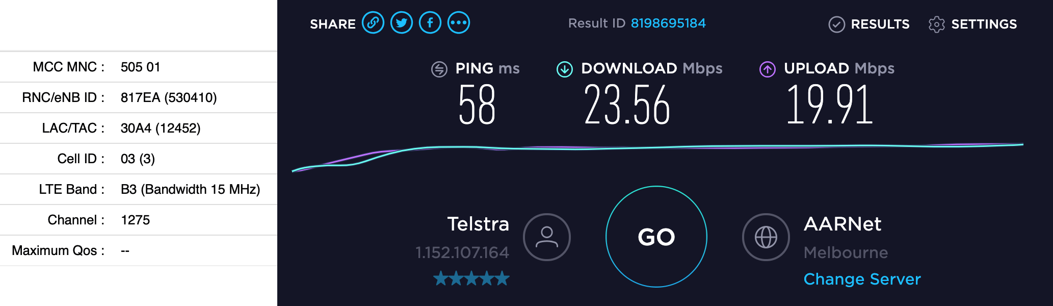
The much better upload on B3 is likely due to the antennas being a better match at that frequency, but the download speed is probably lower due to the vehicle moving (no I wasn’t driving), network congestion and the lower bandwidth of the cell tower.
In summary, the speed is improved compared to what I was seeing before (PPP Serial never went much beyond 20Mbit), the connection seems more stable (didn’t drop out once with several hours of testing), and I can actually see the modem parameters.
I might investigate some alternative antenna options to replace at least one of the glass-mount antennas and see if things improve. I’m not convinced they were such a good choice, at this point, and having mounted other antennas on the car, it turns out not to have been that hard to do it properly. Also, I should dig up a GPS antenna and see if I can get the GPS on the card working, as that could be useful.