Building an End Fed Random Wire Antenna
I’ve previously covered building a multi-band linked dipole Inverted V antenna on here. This antenna has been a great performer - when and where you can set up the pole, get the angle on the V correct and keep other stuff out of its near field. Failing to do this will result in a VSWR that’s a little less than great.
And with the Codan 9323 running in addition to the Icom 7100 on some radio-based outings, a second HF antenna was needed.
I decided to build an end-fed random wire. It’s a compromise on performance but it’s much more versatile and easy to deploy.
The concept is pretty simple - the ground goes to ground, and the signal goes to a random length of wire that goes from somewhere to somewhere. When the wire is less than about 3/4 of a wave at the operating frequency, the radiation is broadside to the wire, with spiky lobes growing as the wire lengthens. As the wire lengthens further, at a few wavelengths, the radiation is along the wire instead. But that’s for a wire in free space in a straight line - your results will vary in the real world.
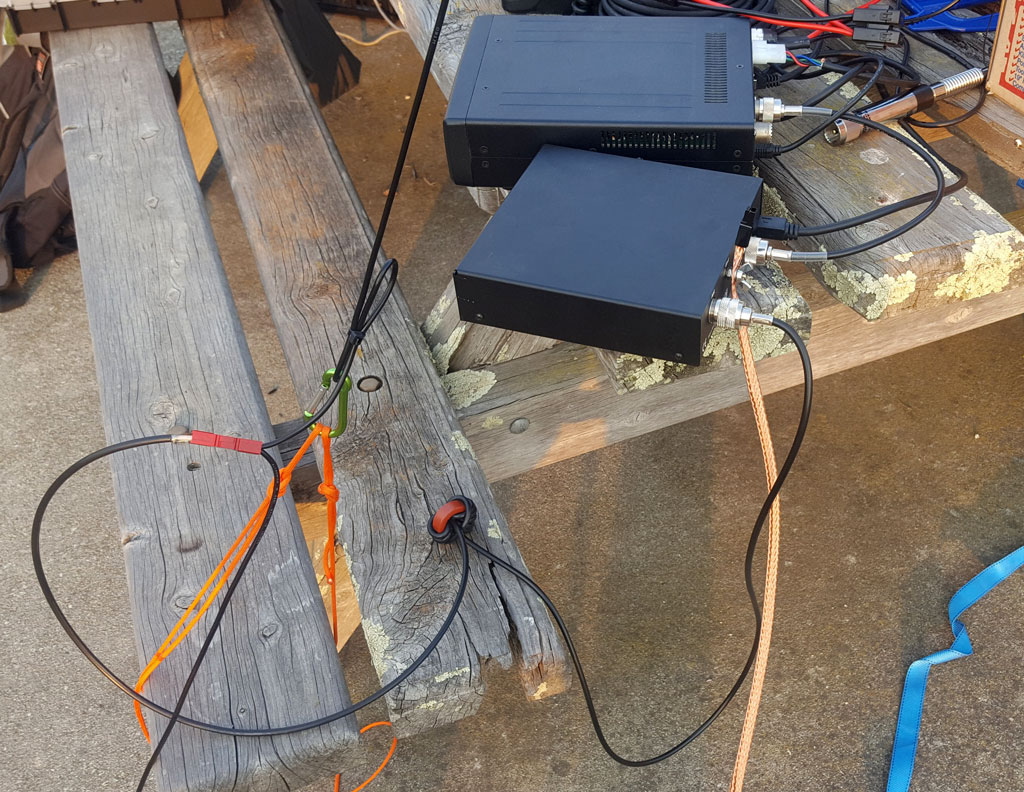
This was attempt #1 - and if you’ve not seen RG-58 coax crimped onto an Anderson PowerPole… well, you have now. However, there were a few problems - there was an instant and major RF-in-the-shack problem - things started behaving strangely and everything got crashy. The antenna tuner also couldn’t always tune it either - the impedance fell outside the range it could handle.
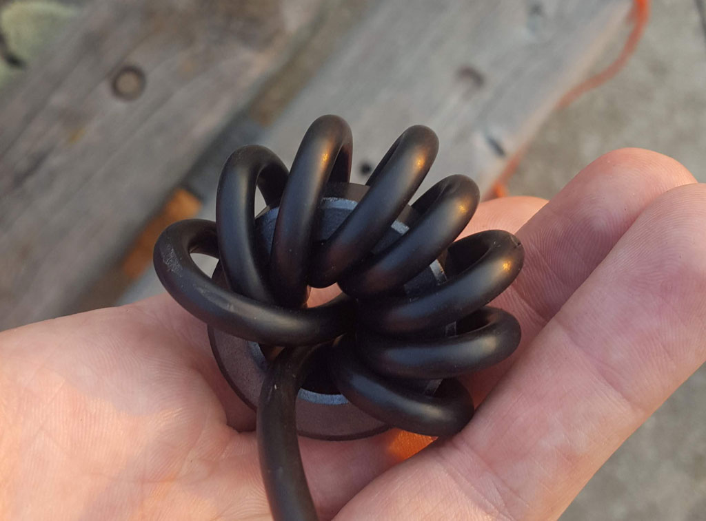
Swapping out the iron powder toroid for a ferrite one didn’t improve things much - there still wasn’t enough common mode choking so output power was kept low…
One major issue with the length of wire being random is that it’ll almost never the right length at any frequency you want to operate on. This means it will have a very high impedance in the range of hundreds of ohms for most frequencies, rising to thousands if it’s close to a half wave.
So how can we solve these problems? The feed point of the inverted-V antenna uses a 1:1 balun to convert between the 50 ohm coax input and the close-to-50-ohms balanced inverted-V. Instead of a balun, we’ll use a device that is unbalanced on both ends - the unun.
We’ll use one with an impedance transformation ratio of 9:1, meaning our 50 ohm input is matched to a 450 ohm output, which is a closer match to the impedance of our random wire at most frequencies.
To build it, I mostly followed the instructions from VK6YSF, but instead of terminating the connections in binding posts, I used Anderson PowerPoles to match the ends of my random wires.
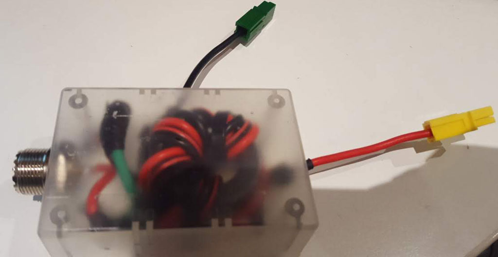
I cut two lengths of random wire and folded them back to allow a carabiner to be clipped between them.
Here it is being tested for the first time in the park - with the wire being looped over two tall trees.
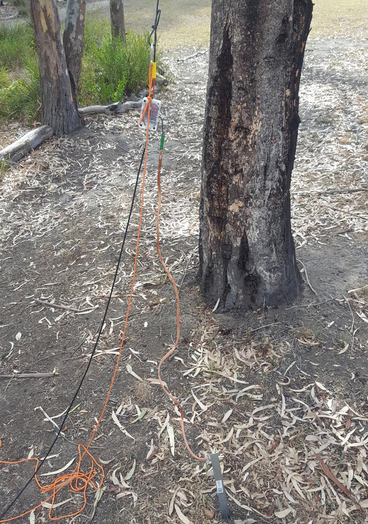
Depending on wire length, you may not need the tuner for certain bands. Initial testing with the random wire I picked (I’d measure it but then it would cease to be a random wire) showed the SWR on 30m and 20m was below 2:1. Using both pieces of wire and the LDG IT-100 tuner, every band between 80m-10m could be worked. The unun seems to handle 40W PSK and 100W SSB perfectly fine - the full power limit of the tuner.
Comparing it with the inverted-V showed it wasn’t significantly worse however we picked a pretty bad weekend to compare. Band conditions at the time were terrible due to geomagnetic storm activity, resulting in propagation being terrible - but we got a voice contact to Adelaide (not far in HF terms). I’ll give it a proper test later and we’ll discuss what can be done to improve things.