Building a Multiband Inverted-V Dipole
Even if I had the space to put up an HF antenna where I live, the noise floor being a constant S9+20 would make actually using it quite difficult. But you can always drive out to a far away place, set up an antenna and get on the air…
The inverted-V dipole is a good choice for this - you need a pole, a balun and a lot of wire.
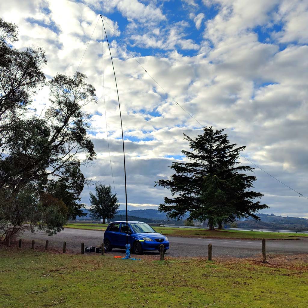
(more guy ropes will make it less bendy when the wind blows…)
Why is the inverted V great? Unlike an ordinary dipole antenna, you only need a single pole. Your wires double as guy ropes on two of the sides, and you may be able to get away without any more.
First, we need a pole. I use the Spiderbeam HD 12m pole, a telescoping fibreglass pole (plain fibreglass, not radiation pattern ruining slightly conductive carbon fibre).
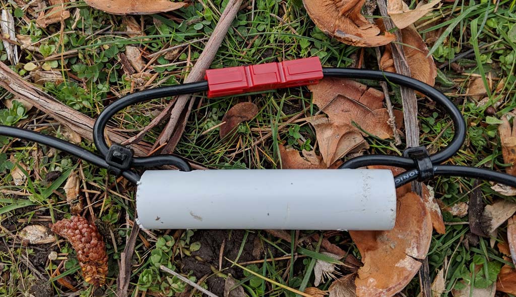
Next we need a balun. We need this to convert the unbalanced signal from the coax to a balanced signal to feed two halves of the antenna. I use the Diamond BU-50 which is good if not a little heavy.
With that balun at the top of the pole, I only use the lower 10m of this pole - the top two segments are a bit too bendy with the added weight on them. I’d imagine that if you fed the dipole with ladder line, you might be able to use all 12m.
But how do we make the antenna operate on multiple bands? We would need to somehow make the wire longer and shorter to make it resonant on the right frequency. We could use an antenna tuner to make this happen, and I personally have a LDG IT-100 tuner - good for mobile use so you don’t need to physically adjust the antenna.
Antenna tuners, though, have their fundamental disadvantages. For one, they don’t actually “tune” the antenna. They’ll make the feedpoint impedances match, but you’ll still be operating on an antenna that’s not efficient at that frequency. Secondly, the cheaper and smaller ones tend to have power limits, especially when matching poor antennas. The IT-100 is limited to just 30 watts for “constant carrier” modes, yet the 7100 is capable of 100w.
But if we’re building the antenna from scratch, why not just have it be the correct frequency?
The linked dipole is a simple concept. It’s a dipole, which you can add and remove pieces from to have the right length.
Essentially, you start by making your inverted-V antenna for the highest frequency you want to operate. Use a calculator like this one to calculate the length of the inverted-V. Cut the antenna cable about 0.6 - 1.0m longer than the number it gives you, put the antenna up and check SWR on the desired band. Take it down, cut it a little shorter - remembering that you can’t cut it longer if you cut too much off! Repeat until the SWR is acceptable on the target band, add your desired connectors and continue.
I’m not exactly sure why this happened, but all of our elements came out about 5-6% longer than the calculator said they should have been - it pays to cut long and shorten later…
This one uses Anderson Powerpole connectors because this seemed like a good idea at the time. They’re capable of dealing with high voltage, easy to crimp and easy to connect and disconnect.
Continue building additional segments until you reach the lowest band you want to operate on. This antenna is capable of operating on 40m, 30m, 20m and 15m. 10m was skipped because its propagation characteristics right now are not good due to being in the least active solar cycle since the invention of radio.
With the tuner, the antenna could be used on 17m, 12m and 10m bands, and could probably get something out on 80m/160m.
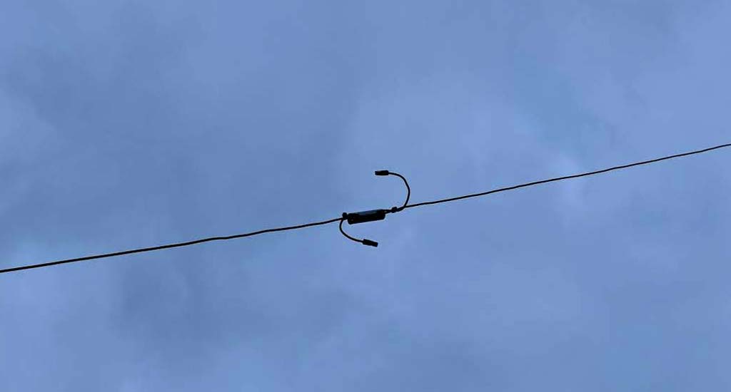
A link here seen unlinked for operation on a higher frequency.
FT8 was tested on all four bands the antenna supports. Previously I’d been limited to 40m, and only able to achieve QSOs with mostly Australia/NZ (other than one with EB2AM) and the same story happened this time - only getting a response out of VK7AC - in HF radio terms, that’s pretty much next door.
However, having the linked dipole, I made successful FT8 QSOs on 20m with JA5JQH, N7AY, ZS6JES, AH6SZ, WL7CG and KJ0I. On 30m, K7QDX and F6BHK were worked and on 15m, EA5GHD (15m was very quiet).
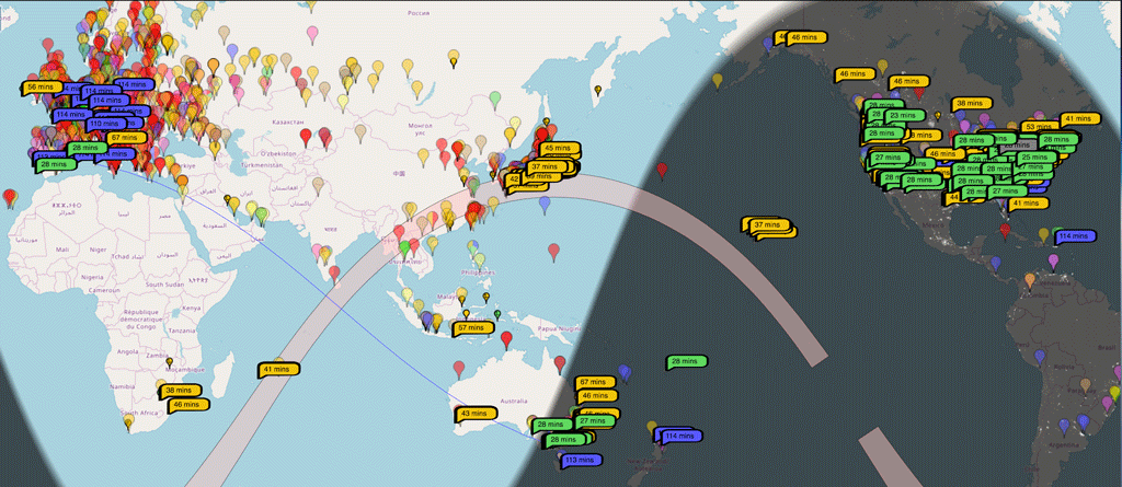
PSKReporter screen shot: blue = 40m, green = 30m, orange = 20m. No reports showed up for 15m even though I had a successful contact.
In future, we’ll try building some additional segments to get the dipole on 80m. This would require the angle to be lowered - currently it’s at 45 degrees, giving you 14.4m of element length to the ground. For 40m, this puts the ends of the element a few metres off the ground - a good thing when they’ll be at a potential of several hundred volts while transmitting. For 80m, this will be 20m a side, to which a 30 degree angle would be able to work, however the base would have elements almost all the way to the ground, 17m away.
Still, I’ve got 94m left of a 100m roll of cable from Altronics…