ESP8266 MQTT Serial Projector Remote
In the bedroom, there’s a media centre box attached to a projector. The projector in question is attached to the bed, pointed upwards at the ceiling, but that’s another story for another day…
Originally, I wanted the projector to be automatically switched on and off with the media centre. The projector has a RS232 serial port for control, so it was just a case of connecting this to the media centre with an appropriate cable and writing a few scripts to send commands on startup and shutdown.
However, I’ve just replaced the ancient AMD E350 based Mini-ITX box with a shiny new OSMC Vero 4k, an ARM-based box that you don’t really shut down.
Although I could still do this on the Vero, I decided to implement it as a standalone device. Take an ESP8266 NodeMCU board (a nice breakout board for an ESP-12 module) and combine it with a TTL to RS232 adaptor. Then, write firmware for it that connects to a MQTT server, and we’ll be able to control the projector from the web interface of HomeAssistant or any of the Amazon Echo devices.
Some searching reveals a PDF with the commands to turn on and off the projector: <CR>*pow=on#<CR> and <CR>*pow=off#<CR>. Given that all the commands start with <CR>* and finish with #<CR>, I decided to implement a feature on the ESP8266 side that allows you have this automatically added to the start and end of every command.
This means the config in HomeAssistant can just look like this:
switch projector:
  platform: mqtt
  name: "Projector"
  command_topic: "/serial/projector"
  payload_on: "pow=on"
  payload_off: "pow=off"
The code for the ESP8266 side is available in GitHub at gm_stack/esp-mqtt-serial.
Checkout the code and copy config.example.h to config.h and edit settings as appropriate. If you don’t have a BenQ projector, you’ll need to edit the serial_* settings too.
#define wifi_ssid "ssid"
#define wifi_pass "password"
#define net_hostname "mqtt-serial"
#define mqtt_host "mqtt.example.org"
#define mqtt_port 1883
#define mqtt_user "mqtt_user"
#define mqtt_pass "hunter2"
#define mqtt_topic "/serial/projector"
#define serial_baud 115200
#define serial_head "\r*" // BenQ
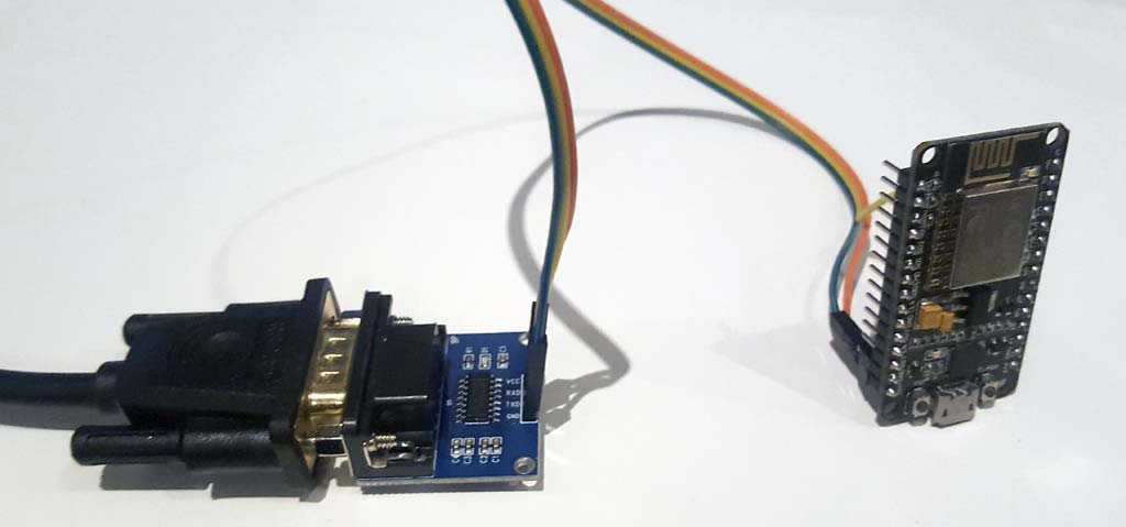
#define serial_tail "#\r"The wiring is simple:
- GND on the NodeMCU to GND on the RS232 adaptor
- Vin on the NodeMCU to Vcc on the RS232 adaptor
- D4 (GPIO2) on the NodeMCU to TxD on the RS232 adaptor
Why GPIO2? It’s the TxD line for the ESP8266’s secondary UART. Using this one for the commands leaves the primary UART (connected to the NodeMCU’s USB-Serial chip) available for status/debugging messages.
Still to do on this:
- 3D printed case
- Watchdog support in case ESP locks up / suffers anything unexpected
- Web server for config / settings / status
- Use WiFiManager instead of hardcoded SSID/password
- Try other commands to change input modes and projector settings - could be handy if I ever connect multiple inputs