Baofeng T1 Volume Mod
Previously we covered the Baofeng T1 Mini and there was one major complaint - it’s way too loud.
So let’s crack it open and fix it up.
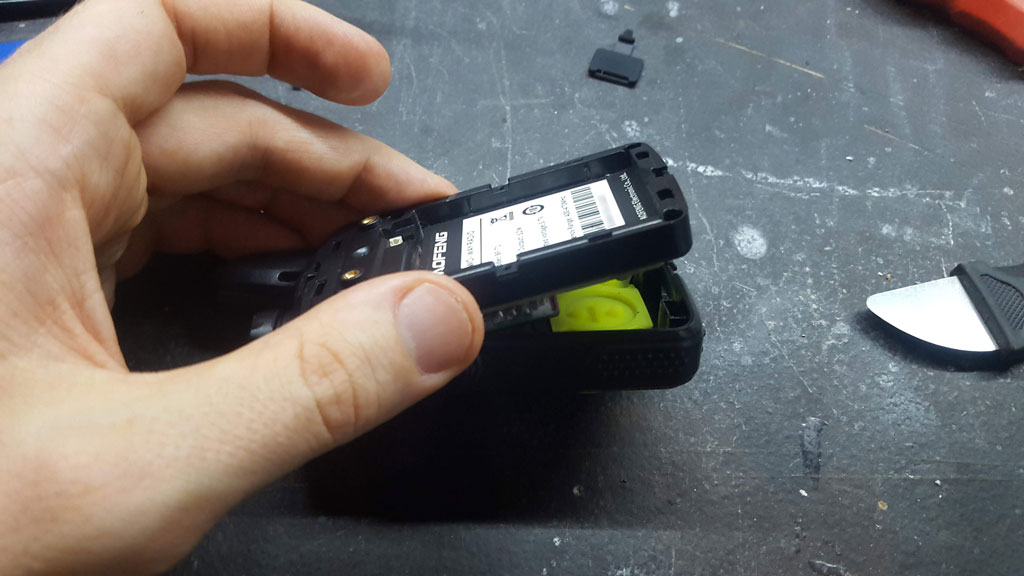
First, remove the belt clip, the back panel, the battery and undo the four screws holding the radio together. Using a long instrument, lever the two halves apart through the bottom holes in the radio.
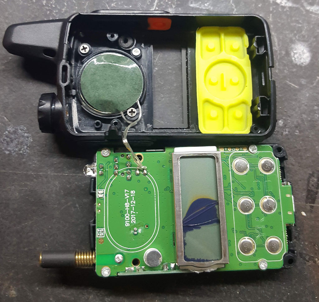
Flip out the other side (I did this first on one of the broken ones so I didn’t risk breaking a good one) and undo the four screws holding the PCB to the plastic.
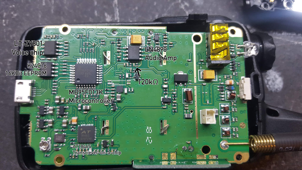
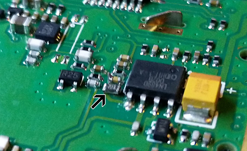
As we can see on the board:
- MB95F013K microcontroller, same as the UV-5R - sadly write-only, not reprogrammable.
- AT1846S radio chip, also the same as the UV-5R (supports UHF/VHF but as we said before, filters are not included for correct VHF operation)
- K24C16 16KBit EEPROM (2KByte) - with 2KBytes of EEPROM, why only 20 channels!?
- LT-ZY801 voice chip (presuming this is similar to the LT-ZY606 in the UV5R).
- LN4890 audio amplifier chip with incorrect value resistor on it.
I haven’t had luck decoding the smaller chips - the following are still unidentified:
- N729 N987 (centre)
- T260 PN8S (bottom left)
There’s a broadcast FM receiver and a Li-Ion charger still to be found somewhere in there. Maybe the above two chips?
Now, why is it too loud? According to this document the reference design specifies a 20kΩ resistor on the input. The suggested solution is to solder a 33k resistor in parallel with this one, across the legs of the IC to avoid having to do fine soldering - but I’d rather just replace the resistor.
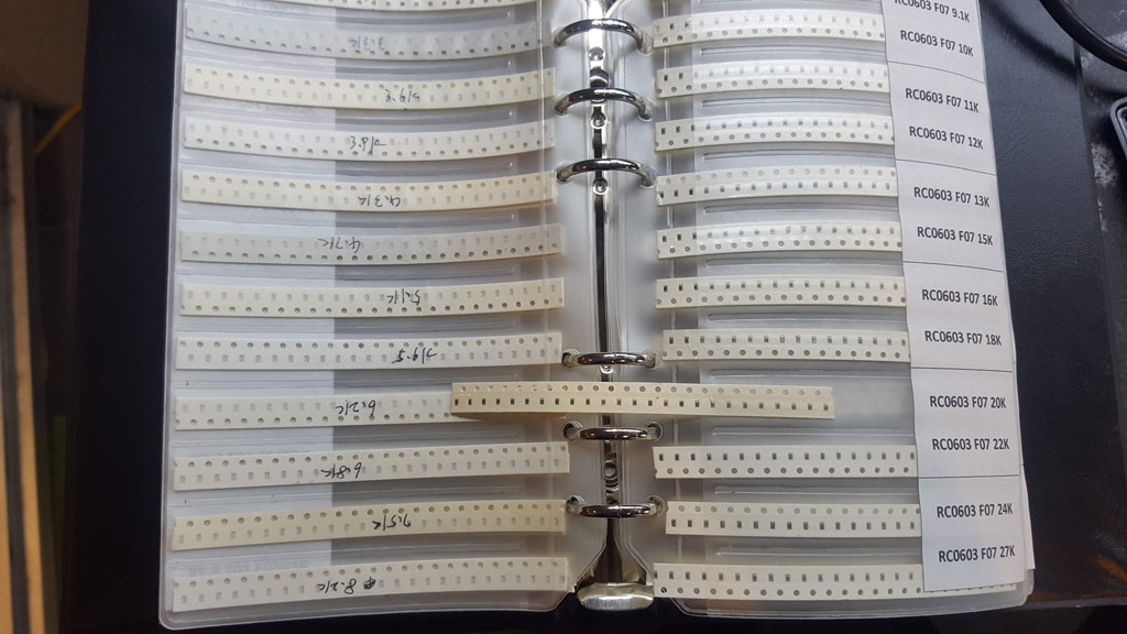
I grabbed my 0603 sample book and flipped to the page containing the 20k resistors - only to find that the ones on the board are actually the even smaller 0402 size. I don’t have an 0402 sample book, unfortunately, as I didn’t think I’d be messing with resistors that small.
We can still make this work though - there’s enough pad overlap to solder it on, even if it is too big. Remove the 0402 resistor first.
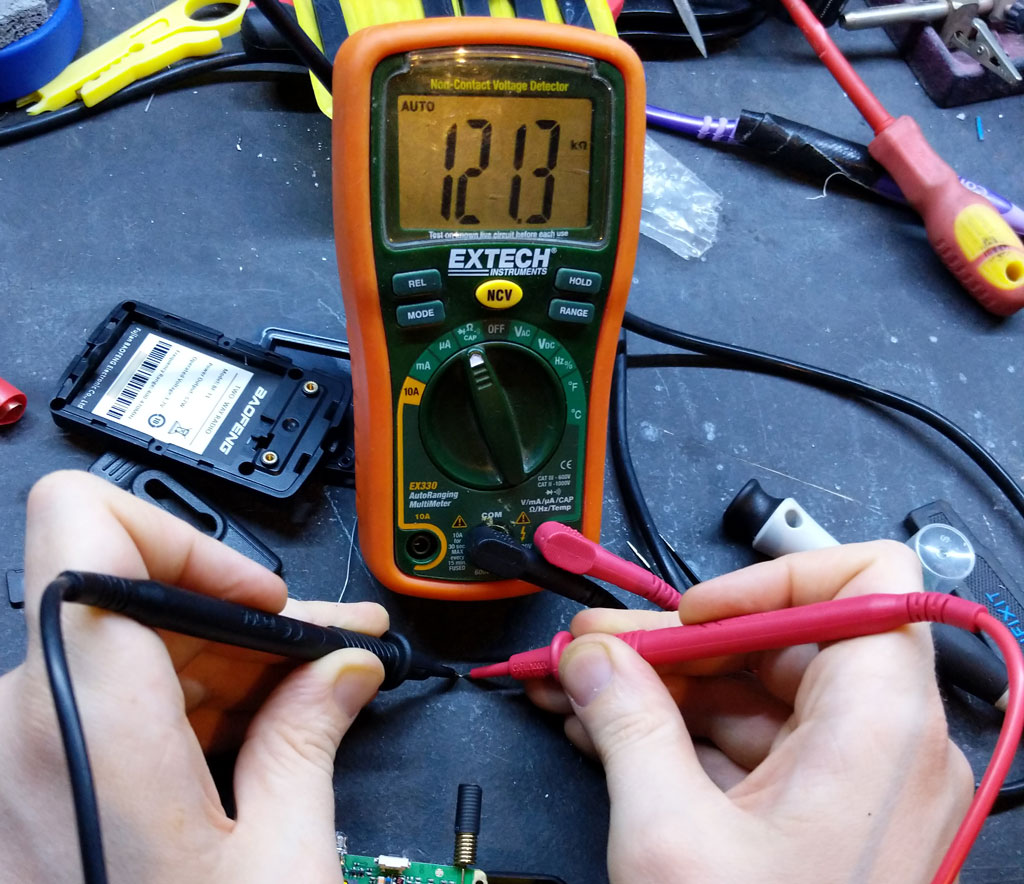
You can see here exactly how small it is, and after having desoldered it, it turns out that it is actually 120kΩ rather than the 100kΩ mentioned in the above document. Regardless, we’re replacing it entirely with a 20kΩ, so it doesn’t matter what it was.
After removing the resistor, add a little solder to both pads. Hold the new resistor in place with tweezers, apply heat to the side nearest the IC, melt the solder and slide it a little towards the IC until it’s centred over the pads. Then heat the other side to melt the solder and connect it. It’s probably not a recommended technique but it worked for me.
Reassembly is the reverse of disassembly, and you should now notice that the radio is at an appropriate volume.
Still to do:
- TX audio is a little quiet. This is a bit hard to fix on the UV-5R with a similar chipset - is it similarly difficult here?
- Beeps are still a bit too loud - find out where they’re generated, and swap another resistor out?
- Replace the LED with an even brighter one?